
By Mark Elo
When it comes to testing and verifying electronic systems, the right tools can make all the difference. Among these essential tools is the signal generator, a device critical for creating electrical waveforms to stimulate a piece of electronic equipment. Here at Tabor Electronics, we understand the significance of precision and reliability in these devices, which is why we've refined our technologies over the past 50 years to offer you the best possible solutions.
In this guide, we will examine the following:
- How a Signal Generator Works
- Choosing the Correct Supplier
- Product Specifications Highlights
How Signal Generators Work:
Frequency Synthesis
A. Definition
The dictionary’s definition of frequency synthesis is the ability to generate a range of frequencies from a single fixed time-base or oscillator – what is often referred to as the reference.
There are multiple types of synthesis techniques that either fall into the category of direct synthesis – with multiple implementations and both analog and digital designs – or indirect synthesis which is usually an analog implementation.
B. Synthesis Types
Direct Analog Synthesis
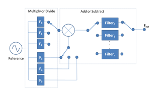

Figure 5a. Direct Analog Synthesis
Direct synthesis is based on analog frequency translation techniques - it is a combination of analog multiplication, mixing, and filtering stages. When higher frequency resolution is required the more complex the combination of stages becomes, however in terms of noise performance, frequency stability, and frequency switching speeds this is the most superior synthesis technique.
Direct Digital Synthesis (DDS)

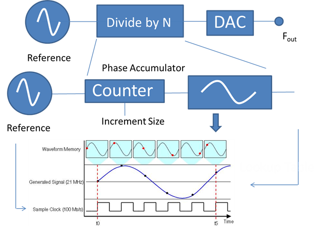
Figure 5b. Direct Digital Synthesis (DDS)
A direct digital implementation stores a waveform in memory, then using and a counter you clock through each memory location at different speeds to produce a relevant frequency. This in effect is a frequency dividing system not multiplication and addition systems like the Direct Analog System. However, the DDS can be used in multiple Nyquist zones to produce higher frequencies. This is explained in Topic Four Section C. RF Digital to Analog Converters and Multiple Nyquist Zone Operation
Indirect Analog Synthesis

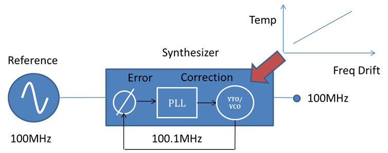
Figure 5c. Direct Digital Synthesis (DDS)
The indirect synthesizer is based on Voltage Controlled Oscillator (VCO) or a YIG tuned Oscillator (TTO) and uses a Phase Locked Loop (PLL) Architecture. The VCO can create a frequency based on a voltage level. The accuracy of that signal is determined by the error between the phases of the reference and the VCO frequency. The PLL compares the phase and produces an error correction voltage.
Arbitrary Waveform Generator
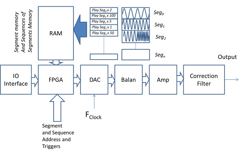

Figure 5d. Arbitrary Waveform Generator (AWG)
An arbitrary waveform generator (AWG) can store multiple waveforms in its memory. These waveforms can be created by specific tools either provided by the manufacturer of the AWG or by using a tool such as MATLAB and Octave. The user can index and play waveform memory combinations. Like with the DDS the highest frequency is a function of the sample clock and waveforms can be generated in various Nyquist Zones.
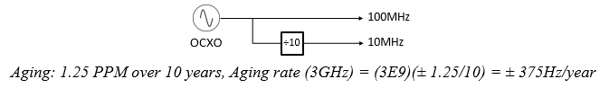
C. The Reference Oscillator
The reference is fundamental as by our definition of synthesis earlier – all our frequencies are derived from it. It also contributes to the quality of the synthesis we wish to perform in our signal generator. Quality can be defined by frequency stability - short term stability, or phase noise. Long term stability is defined by aging or frequency drift. There are multiple references available all with different price points and performance characteristics. Some are built into the signal generator and are based on Oven or Temperature controlled Oscillation Techniques (which are referred to as OCXO, TCXO) and external references that can be derived from a cesium time base (atomic clock) or the GPS system.
Frequency drift is defined by changes in temperature and the aging specification. In this example, you can see when lucid is tuned to 3GHz it drifts 375Hz over a year. This is a factor of 10 improvements over similar signal generators.
If you want to have a number of signal generators phase locked with each other, you would share a single reference between multiple synthesizers or signal generators as shown in 6a.


Figure 6a. Reference Sharing Between Multiple Synthesizers.
In this scenario, we have a single reference being shared between two VCO-PLL synthesizers. If 10MHz is the reference frequency with 0.1° Phase Drift, this will produce a 10° Phase Drift at 1GHz. By changing the reference to 100MHz you receive a ten times improvement. However, this will still cause significant frequency drift problems at higher frequencies. One way to compensate for this is to use a higher reference frequency, preferably in the GHz range. In the example, the Tabor Lucid signal generator is set to 4GHz and with an oscilloscope set to maximum persistence then monitored the two locked sine waves for 15 hours. While not a quantitative measurement, qualitatively it does show there is minimal drift between the two channels over time and temperature at 4GHz.
Phase Noise

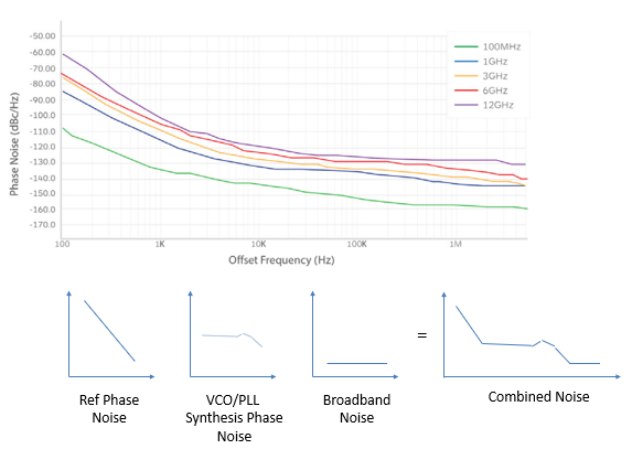
Figure 7a. Phase noise plots
A single side band phase noise measurement is usually used to describe the stability of a synthesizer. In Figure 6a, you can see several effects are in play. The measurements are relative to the carrier and, that carrier would be to the left of the y axis and is often excluded from this type of plot. One phenomenon we observe is the phase noise performance decreases at higher frequency multiples with a rule of thumb of 6dB decrease in performance every time you double the frequency.

Figure 6a can be deciphered in terms of each element of the synthesis technique. Close to the carrier the phase noise is usually related to the reference frequency and has a steep slope, then from around 1kHz to 100MHz you see a plateau based on the noise contribution of the VCO, and finally, as you move further away from the carrier broadband noise becomes the dominant factor.
D. Signal Conditioning – Output Section
The final element that determines a signal generator from a synthesizer is the output section. The output section of the signal generator provides us with the required amplitude. It allows for AM modulation, provides gain and attenuation, and ensures that the absolute levels of the generated signal fall within a specified limit. The amplitude range is enabled using attenuators, and in the case of the Tabor Lucid signal generator will allow a signal range of +15dBm to -90dBm to be generated. Up until now, we’ve specifically looked at phase noise, but there are more phenomena that contribute to a degradation in spectral purity. While poor filtering in the synthesis process can cause Harmonics, the active components used to amplify the signal will cause intermodulation, harmonics, and degradation of the broadband noise floor. Intermodulation is caused by two or more carriers constructively interfering with each other and creating a frequency-related side band. For every dB increase in the carrier, a harmonic will equally increase. For intermodulation, the sidebands increase by a factor of two or three depending on if it is a third order or second order product. The spectrum trace shows the third order harmonics 2f1 - f2 and 2f2 – f1, an example of a second order intermodulation product would be f2-f1, f2+f1. The center plot shows the Harmonic performance of over 60dB’s and finally the third plot represents the broadband noise floor.


Figure 7b. Typical Output Section
The Tabor Lucid Signal Generator encompasses all of the above techniques, and our engineers have optimized each subsystem for the smallest foot print, best heat dissipation, and the highest specifications we can achieve.
Why Choose a Specific Supplier: Tabor Electronics?
-
Experience and Expertise: Tabor Electronics has over five decades of experience in developing high-quality, small-footprint designs. Our products provide high levels of RF isolation, crucial for minimizing interference and maximizing performance.
-
Modularity: Our Lucid Series signal generators are based on a modular technology that can be customized for various applications, whether embedded, benchtop Instrumentation or ATE setups.
-
Rugged and Reliable: We also offer the only handheld analog portable signal generator on the market, renowned for its precision and durability even in the most challenging environments—from the Amazon Jungle to the Andes mountains.
Product Specification Highlights: The Lucid Series
The Lucid Series of RF analog signal generators stands out with its industry-leading performance, offering a range of models that cater to different frequency needs:
- LS3081D, LS6081D, LS1291D: These models are perfect for applications requiring up to 12GHz, providing an amplitude range of -130dBm to +30dBm with capabilities like advanced modulation and an intuitive GUI for ease of use.
- LSX Series: Extending up to 40GHz, the LSX models are ideal for mmWave applications, combining all the advanced features of the Lucid series with extended frequency capabilities.

Figure 8: LS Family Phase Noise Plot
Practical Applications
Whether you're working on installing field equipment, testing analog to digital converters, or developing wireless communication systems, our signal generators provide the necessary performance. With options for multiple channels and phase-coherent outputs, they support a wide array of applications, including:
- Testing and Characterization: Use our generators for mixer testing, amplifier distortion characterization, and more.
- Field Use: Our portable units are designed for easy transport and use in field settings, ensuring reliable performance no matter where you are.
Learn More
To delve deeper into the specifics of choosing and using signal generators, and to understand how our Lucid Series can be tailored to meet your specific needs, visit our RF Signal Generator Resource Center. Here, you'll find detailed information, expert insights, and more to help you make the most informed decision for your testing and measurement requirements.
For any questions or to schedule a demo, don't hesitate to contact us. Our team is ready to assist you in selecting the perfect tool that matches your exact needs, ensuring precision and efficiency in all your projects.